Initiation system
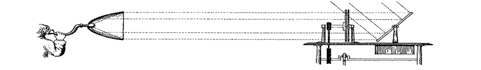
A general Diagram of the experimental setup of the photoacoustic calorimeter is given in Figure 1:
Figure 1. Diagram of the experimental setup of the photoacoustic calorimeter. NL: nitrogen laser; I: iris; OT: optical trigger; F: filter support; L: collimating lens; BS: beam splitter; CC: calorimeter cell; CM: calorimeter microphone; CP: calorimeter preamplifier; O: digitizing oscilloscope; P: pyroelectric probe; PP: probe preamplifier; EM: energy meter; SC: spectrophotometer cell; SP: spectrophotometer; PC: personal computer; RC: reference cell; RM: reference microphone; RP: reference preamplifier; RR: reference reservoir; RPP: reference peristaltic pump; VT: Viton tubing; SR: sample reservoir; TT: Teflon PFA tubing; V1: purge valve; V2: perfusion valve; S: syringe; AM: argon manifold with two reducing valves; T1 to 3: thermistors; M: multimeter; TIB: thermally insulated box; HE: heat exchanger; TB: thermostatic bath with temperature controller.
The initiation system consists of a laser (NL) and the necessary optics to lead the beam with the adequate characteristics to the calorimetric cell (CC). The laser (PTI PL 2300 nitrogen laser) emits pulses at 337.1 nm with 800 ps duration. The optical components, aligned between the laser and the calorimetric cell, consist of an iris (I), a filter support (F), and a collimating lens (L). The iris (Newport M-ID-1.5) is used to cut out most of the laser output and allow only a thin cylinder of light to pass through its aperture, set to ca. 2 mm. The laser energy that reaches the cell is further controlled by the use of neutral density filters (Newport FSQ-ND(A), A = 003, 01, 03 and 05). These are placed on the home-made support in various combinations, to a maximum of three simultaneously, allowing the laser energy to be lowered in steps to about 10 % of the total. The collimating lens (Newport SBX-031 mounted on M-ALM-2) focuses the beam just before the calorimetric cell, where it arrives with a width of ca. 1 mm. An optical trigger intercepts the beam right after the iris to provide the signal that initiates data acquisition (setting the zero-time for the photoacoustic waves). The calorimetric cell is a standard quartz flow-through cuvette with 10 mm path length (Hellma 174-QS), which is placed on top of a piezoelectric transducer (CM). A home-made brass press holds the two in perfect contact (a small amount of Apiezon-N is used to improve the signal transmission from the cell to the transducer). All the above mentioned components are mounted on an optical bench (Newport XSN-33) with standard holders (Newport M-VPH-2) and posts (Newport M-SP-4 or 8), which allow them to be vertically adjusted. Both the lens and the calorimetric cell-transducer block can be further adjusted horizontally by means of translation stages (Newport M-TSX-1A), parallel to the laser beam in the case of the lens, and perpendicular to it in the case of the cell-transducer block. The laser is mounted on a separate table, adjusted in relation to the rest of the system. Best results are obtained when the laser hits the cell at ca. 2 mm from the base. The laser energy reaching the cell with this geometry, measured with the pyroelectric probe (see below) when the cell is filled with solvent (benzene, spectroscopic grade or better) and without any attenuating filters (‘blank conditions’) is ca. 30 μJ.
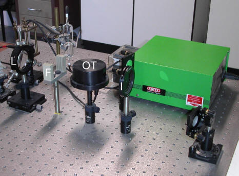
Figure 2. Detail of the initiation system, showing the iris (I), the optical trigger (OT), the filter support (F) and the collimating lens (L). The nitrogen laser (not shown) is to the right.