Temperature measurement and control system
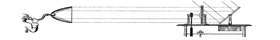
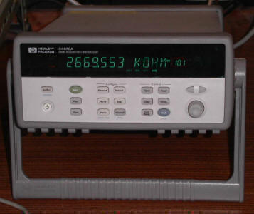
The temperature measurement system consists of two Teflon encapsulated thermistors (T), connected to a Hewlett-Packard 34970A multimeter equipped with a HP 34901A 20-Channel Armature Multiplexer. For each thermistor (Omega 44104) a calibration equation was obtained in which the electrical resistance is converted into temperature. Calibrations were performed against a quartz thermometer (HP 2804A). The sensors are placed in a specially design glass adaptor, allowing the determination of the temperature of the flowing solution at the entrance and at the exit of the calorimetric cell.
.jpg) |
 |
 |
|
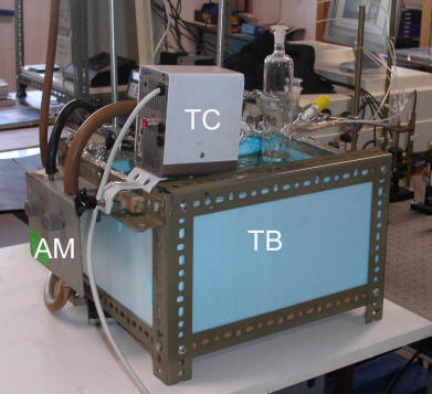
Figure 1. Main components of the temperature control and measuring system: thermistors (T,T), multimeter (M), temperature controller (TC), and thermostatic bath (TB). The argon manifold (AM) with two reducing valves is also shown.
To allow faster temperature equilibration and better temperature control overall, the calorimeter cell was latter placed inside a thermally insulated polimethacrylate box (TIB) containing two metal heat exchangers. Small holes were drilled in the laser path and to allow the connections of the transducer cable, the pyroelectric probe, the thermistor cables, and the sample flow tubes. The heat exchangers are attached to the box walls parallel to the laser path. Another heat exchanger (HE) is used to heat the sample flow tube, again to ensure a rapid temperature stabilization inside the cell. Temperature control is attained by using a water bath (TB) with a Haake D8 temperature controller (TC) and a Thermo Haake EK20 cryostat (not shown). Liquid from this thermostatic bath is circulated through all heat exchangers. Temperature determination accuracy is better than 0.05 K.
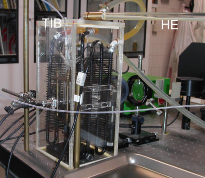
Figure 2. The calorimeter cell enclosed in the thermally insulated box (TIB). The solution is delivered at the same temperature through the heat exchanger (HE). This complex-looking mesh of tubes and wires sits at the top of the optical bench of our PAC setup.