
Transmittance measurement system
In our calorimeter we have implemented two independent systems to measure the sample transmittance. The first system uses a pyroelectric probe (P) that measures the laser beam intensity just after the calorimetric cell. The signal is then amplified (PP) and stored on a energy meter (EM). This is finally connected to the computer (PC) through a RS-232 interface for data acquisition and control. The probe (Gentec ED-100) is mounted on a home-made holder on the optical bench located at about 2 cm after the calorimetric cell. The probe is connected via the same shielded coaxial cables as before (BNC50) to the pre-amplifier (Gentec EDX-1), set at a 100-fold gain, and then to the energy meter (Gentec EM-1), calibrated according to the probe specifications. The detection limit of this system is 1 mJ.
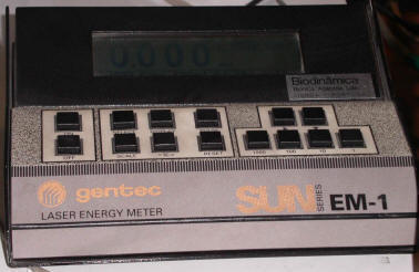
Figure 1. Energy meter.
The second system to measure the transmittance (Figures 2 and 3) is based on a spectrophotometer (SP) whose sample cell (SC) is also a standard flow-through quartz cell, identical to the calorimetric cell from where the solution is flowed. This option needs a referencing system to allow normalization of the photoacoustic signal, basically a incident laser energy measuring system.
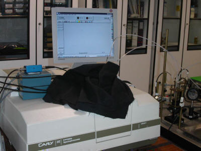
Figure 2. Spectrophotometer.
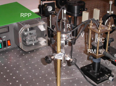
Figure 3. The transmittance measurement system using a spectrophotometer, showing the reference cell (RC) and microphone (RM), the reference reservoir (R), the peristaltic pump (RPP), and the Viton tubing (V). The beam splitter (BS), placed to the right of RC, is not shown.
In our calorimeter the laser energy is monitored using the photoacoustic effect itself. Part of the laser energy is deflected using a beam splitter (BS) to a duplicate of the main photoacoustic measuring system which includes a reference cell (RC), a piezoelectric transducer (RM) and a pre-amplifier (RP), all identical to their main counterparts, and connected in the same way to a second channel in the oscilloscope. The reference cell contains a ca. 1.0 absorbance solution of ortho-hydroxybenzophenone in iso-octane, producing a ca. 100 mV photoacoustic wave for the geometry and the conditions mentioned above (blank conditions). The beam-splitter (Newport M-PBS-2) is mounted on a holder and post of the same types as before and its orientation can be fine-tuned via a rotating-base (Newport M-RSX-1M). In our calorimeter the beam-splitter makes a 48° angle with the incident beam, which corresponds to a deflection of ca. 10 % of the incident laser energy to the reference cell. A certain amount of reference solution must be kept flowing through the reference cell. In our calorimeter, a volume of ca. 30 mL is flowed from a glass reservoir (RR) through the cell and again to the reservoir in a closed loop of Viton tubing (VT), using a peristaltic pump (RPP). The pump (Watson Marlow 503 S/RL) operates typically at 2.5 r.p.m. The main component of the second transmittance measuring system is a spectrophotometer (Cary 3E UV-Vis). The working wavelength can be selected with great precision at 337.1 nm, corresponding to the laser beam wavelength. The spectral bandwidth (slit width) is set at 0.5 nm, and the signal averaging time is 3 s (corresponding to an average of 90 readings for each measurement). The spectrophotometer reference cell is a standard (non-flow) quartz cell (Hellma 100-QS) containing the solution (or pure solvent) corresponding to the experiment blank. The spectrophotometer is also connected to the computer via a GPIB interface (Varian IEEE-488) and controlled in concert with the other measuring devices.