Sample flow line
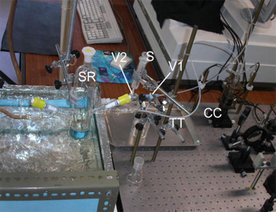
The flow line starts at a specially designed Schlenk-type glass reservoir, from where the solution is impelled throughout the calorimeter via a small positive pressure of argon in the reservoir. Teflon PFA tubing (TT) was used for the flow line since, unlike normal PTFE Teflon, it is impervious to oxygen. Some glass-Teflon adapters were built in order to ensure airtight connections throughout the flow-line. A system of inter-connected three-way valves (Cole-Parmer G-06473-15) is located near the end of the flow-line. The first one (V1) is used to purge the system and the second (V2) allows the introduction of solvent to clean the line through a syringe (S). The flow-line comes full circle at a Y-shaped mini-manifold (AM) that controls the argon entrance in the system. The argon pressure can therefore be used to impel the solution through the calorimeter during an experimental run and, at the end, by using a different configuration for the V1, V2 and needle valves, to clean the line with solvent in the opposite flow direction.
 |
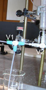 |
Figure 1. Sample flow-line, showing the sample reservoir (SR), the syringe (S), the purge (V1) and perfusion valves (V2), the calorimeter cell (CC) and Teflon PFA tubing (TT).